30th Annual Small Satellite Conference

Members of the STF-1 team have been visiting Logan, Utah, home of the Space Dynamics Laboratory (SDL) and Utah State University for the small satellite conference.  This conference spans a week including a weekend workshop dedicated to CubeSat Developers where Matthew Grubb presented on the NASA Operational Simulator for Small Satellites (NOS3).
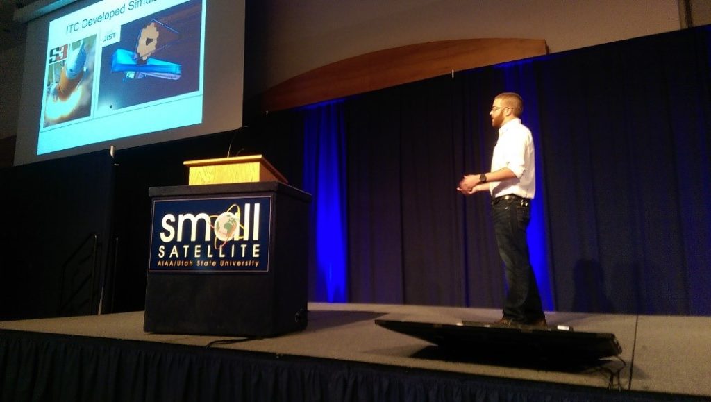
Matthew Grubb presents at the SmallSat Conference.

NOS3 is an open source platform merging in various GSFC technologies into one package.  These include 42, cFS, COSMOS, and NOS Engine.  A full presentation can be found on the smallsat.org website for download.  Additional presentations on cFS can be found as well.  Goddard Space Flight Center also had a booth at the conference presenting on all the current and future planned CubeSat missions such as Dellingr, IceCube, CUTIE, and STF-1.  This included 3D printed models and videos showing simulations of the spacecraft and the assembly process.
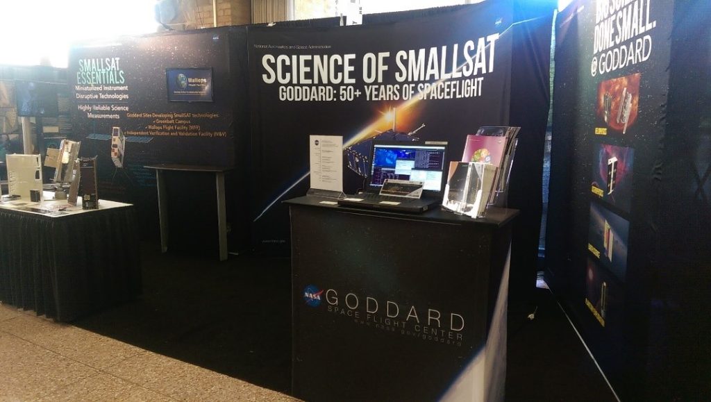
smallsat_booth

Establishing Communication Systems

How important are the L-3 Cadet Radio and the ISISpace Antenna to STF-1? No matter how fascinating the results of STF-1’s multiple experiments are, they aren’t worth anything at all if we can’t view the results on Earth. Because of this, the radio and antenna are vital to mission success. The radio’s “store and forward” capability is what allows it to store up to 4GB of experimental results throughout each orbit, before forwarding the results to the ground station when it is in sight. Additionally, the radio is equipped with a microprocessor that allows the ground team to communicate with STF-1’s on board computer. Ultimately, this system allows the CubeSat to relay data findings and receive commands from the ground team, making it one of the most important systems on West Virginia’s First Spacecraft.

Recently, the STF-1 Team received both the radio and the antenna that will be used in conjunction with it. Pictured below (top), the team runs an initial checkout on the L3 Cadet Radio, while they look over the ISISpace Antenna (bottom).

9

10


If you’d like to learn more about the four science experiments STF-1 will be carrying out in space, make sure to check back on this website over the course of the next several weeks for our new video blog series, where we will interview each of the four teams responsible for the four science objectives on STF-1. Below is a list of each team and their project:

  • WVU Mechanical and Aerospace Engineering – GPS and IMU (Inertial Measurement Unit)
  • WVU Physics and Astronomy – Space Weather
  • WVU Lane Department of Computer Science and Electrical Engineering – III-V Nitride Materials
  • NASA IV&V – Earth Science Camera

While some of these topics may look fairly intimidating, there’s no need to worry. Each of these teams will be explaining their project in terms that we can all understand! Lastly, make sure to get involved with the video blogs by submitting any questions you have for the scientific teams to John.P.Lucas@ivv.nasa.gov. Before each video, we’ll select a couple of the best questions to ask the team we’re interviewing!

Electronic Power System (EPS) Checkout

While STF-1 will be hitching a ride up to the thermosphere on the Electron, once it is deployed, a constant electrical power supply will be necessary for each of its scientific experiments to be carried out successfully. From the GPS to the camera to the radio, most everything on STF-1 requires electrical power to ensure that it functions properly. However, due to the standardized size and weight of CubeSats, STF-1 could never carry enough batteries to power its entire mission. It doesn’t have nearly enough volume, and it’s only allowed to weigh 4 lb! Instead, STF-1 uses 5 solar panels – which are placed on all faces but the bottom – to provide power to the other systems. After converting the sun’s rays to electricity, the solar panels pass the electricity to the ClydeSpace EPS, which stores them in the batteries. Then, the EPS has the ability to send electricity from the batteries to various systems in STF-1.

8

It doesn’t take long to realize that the role that the ClydeSpace EPS plays is a major one, and that the mission can’t afford any mishaps with the EPS’s capabilities. A failure in the EPS would almost certainly result in subsequent mission failure. Above, the STF-1 team performs an initial checkout of the Electronic Power Supply using a laptop, an Aardvark (host adapter), and a power supply. The power supply (pictured in back) simulated the input of electricity that would have been provided by the 5 solar panels. Then, I2C commands were sent from the laptop through the Aardvark to test the EPS. Ultimately, the team found that the EPS functioned well, meaning that it is ready for future hardware testing and that we’re one step closer to putting WV’s First Spacecraft into space!

Initial Weigh-In

The STF-1 team has received all the core components from the various vendors.  These include the chassis and radio from ISISpace, power system from ClydeSpace, radio from L3, and flight computer from GomSpace.  All of these have been inspected and weighed in because weight is a major concern with something so small.  NASA and all launch service providers like to keep the weight as low as possible so that it is easier and cheaper to get everything into space.

7

The GomSpace flight computer with motherboard is pictured above.  This little board is about the size of a credit card and will do all the processing including running our operating system, Free Real Time Operating System (FreeRTOS), and the Core Flight System (cFS) with all our applications to collect and process science data.  This isn’t the only computer on-board, but any data that we want on the ground will have to pass through this one!

Manifested!

STF-1 is scheduled to launch on ELaNA XIX via a brand new rocket called the Electron.  This rocket is currently being built and tested by Rocket Labs USA.  This launch is planned to have an inclination of 85° and an altitude of 500km.  This means that STF-1 will travel around the earth from approximately pole to pole every orbit, will travel around the earth about once every hour and a half, and will be about 100km higher than the International Space Station (ISS) but about 35,000km lower than DirectTV and Dish Network TV satellites!

This announcement brings with it some schedule updates:

Mission Readiness Review: March 2017

Delivery: April 2017

Launch: June 2017

This means that the STF-1 team has under a year to get everything done before delivery!  Even better news is that we have already received our first instrument delivery form the Mechanical and Aerospace Engineering department at West Virginia University.  The Inertial Measurement Unit (IMU) was developed at WVU with the help of the University of South Florida under the Small Satellite Technology Partnership.  The IMU design was miniaturized to overcome the size, weight, and power constraints placed on our spacecraft.  The third generation of the board that has been made custom for STF-1 has 32 sensors on it that will be individually calibrated by student designed rate tables and temperature chambers to give us the best possible data.

Updated information has also been provided by all science payloads allowing us to further update the location of all the components.  The recent model with expanded information is shown below.  This slide was presented at the 13th annual CubeSat Developers Workshop along with a full mission overview.

6

Reaching for the *Laptops*

The Simulation-To-Flight 1 primary objective is, at the most basic level, to be able to run spacecraft flight software on a laptop computer and have it think that it is really in space.  At NASA, we always aim to embrace the goal of “test as you fly, and fly as you test”.   This means developing hardware simulators for each little board or component in STF-1 from the radio to the temperature sensors to make this possible.  The NASA IV&V team has officially named this software package NOS3 or the NASA Operational Simulator for Small Satellites.  This is based on the NOS Engine middleware package developed internally at IV&V.  The objectives are defined as follows:

  • Open source CubeSat risk reduction solution Stars
  • Produce evidence of cost and time savings
  • Develop advanced toolset to identify & resolve software issues
  • Perform meaningful science driven from research and institutions
  • Foster and spread knowledge throughout NASA

The major benefits of this package are the ability to perform flight software (FSW) development earlier, aid in the verification and validation process, perform early application development and payload integration, and mission planning or day in the life activities.  This package is already easy to deploy and begin using.  A sample of what it looks like is provided below.

5

Currently, NOS3 utilizes two open source projects from GSFC.  These include Core Flight System (CFS) and the 42 Dynamic Simulator.  These packages are paired with the open source project COSMOS from Ball Aerospace and custom developed software to provide the full open source solution to users.  The process to make this available to download is currently underway.


How MUSIC Moves Us

The sounding rocket MUSIC successfully launched on March 1st, 2016.  West Virginia University flew multiple payloads including early versions of the Physics and MAE experiments.  These flew approximately 115 miles to apogee and included a VLF receiver, particle detector, and the MEMs IMU.  Data was received from these experiments and is currently being processed at WVU.

4

STF-1 has also selected a high-school and multiple college level interns to aid in the mission over the summer.  Their goals  are to aid in outreach activities by preparing teaching materials,  as well as aiding in mission software development and testing.  The website and blogs will also be updated with progress reports throughout their internships.

In addition to the other interns, a WVU graduate student was selected to aid in the thermal analysis for the mission.  A thermal analysis is needed due to the extreme environment and temperature swings that will occur in low Earth orbit or LEO.  The INSIDE of the spacecraft is expected to fluctuate between -40 and 85 degrees Celsius!  That means that it will be 185 degrees Fahrenheit inside at certain points and that isn’t even the worst case scenario.  Luckily, we can utilize different coatings on the external components to help protect the internal components and keep everything working.

References:

http://www.nasa.gov/feature/music-successfully-launched-from-nasa-wallops

Core Software Development and Hardware Delivery

The Simulation-to-Flight 1 (STF-1) team has been making significant progress since the last blog post.  As per the primary mission objective, some software only simulators have been developed and are currently released as version 1 of NOS3, or the NASA Operational Simulator for Small Satellites.  These simulators will aid in flight software development that is currently underway.  The current focus is on developing the core applications that will drive the mission.  This development phase will last for approximately three months before integration and testing begins.  The clean-room that will be used by STF-1 has been completed and is ready to accept components that have already started arriving.  Below is a picture of the cleanroom ready for the ribbon cutting ceremony here in the coming weeks. 

1

The components have already been arriving and are nearly ready to begin testing.  The science teams have already begun designing systems and PCBs that will perform the experiments.  The current component status can be seen in the table below.  Each science team at WVU has been working diligently to meet the delivery date at the end of this year so that testing can begin.

3

The anatomy of the spacecraft is depicted below.  The chassis selected is the Innovative Solutions In Space three unit design.  This allows for each unit, or cube, to be assembled independently before full spacecraft integration.  The antenna is also specially designed to fit the chassis, depicted on what is actually the bottom of the spacecraft, even though it is on top in the picture.  Having the antennas on the underside of the spacecraft allows for use of the extra space, nicknamed the tuna can due to its size, in the launcher to house the GPS antenna.

2

West Virginia’s First Spacecraft

The development of the first CubeSat to be built in the state of West Virginia, Simulation-to-Flight 1 (STF-1), is underway.  On April 30, 2015, the STF-1 development team held its first table top review to walkthrough the mission plan, technical objectives, components, budgets (mass, power, volume, communications, and cost), risks, and schedule.  The team has identified all major system components.  Components include the GOMspace A3200 on-board computer, L-3 Cadet radio, batteries and electrical power system from Clydespace, and Pumpkin 3U Chassis.  The review was a huge success!

In addition, in late April 2015, the STF-1 team was contacted by the NASA Education Launch of Nanosatellites (ELaNa) effort with respect to a potential launch opportunity and could launch as early as November 2016.  The team is anxiously waiting to hear if we have a launch.

In the meantime, the STF-1 team is pushing forward.  The team is actively working on power simulations to ensure that there is sufficient power generation to support all mission objectives, development of an Advanced CubeSat Simulation Library (ACSL), initiating development of all four science instruments, and beginning to purchase spacecraft components.

The development and demonstration of the ACSL is the primary mission objective and is aimed to reduce hardware reliance and provide a rapidly deployable CubeSat development and test environment.  We are excited about our simulation approach and will go into more details later as the architecture matures.  In the meantime, take some time and submit your best ideas to design the Mission Patch for West Virginia’s first CubeSat in SPACE!

Mission Patch Design: http://www.wvspacegrant.org/wp-content/uploads/2015/04/Mission-Patch-Design-STF1.pdf