The thermal vacuum or TVAC facility is at Goddard Space Flight Center (GSFC), the parent campus of NASA IV&V. This facility has been used recently by the Dellingr team and proved they were ready for flight. First off, what does the TVAC (pictured below) do?
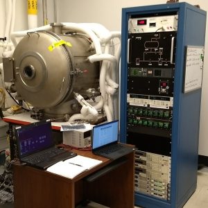
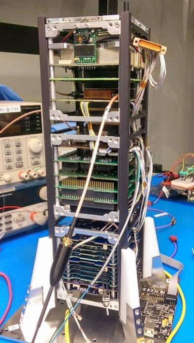
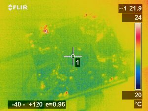
This chamber holds the spacecraft in a vacuum, essentially removing the air around and inside of it. Unfortunately this does not mean the spacecraft floats around inside as gravity still has it’s effect, but this does change the thermal characteristics to those similar to space. Without air the only means of transferring heat to the spacecraft from an external source is through radiation. This is possible due to electromagnetic waves. These same waves are what a thermal imaging camera detects, showing hotter objects as brighter colors and colder ones darker. The image below is of a deployed antenna system heating up while running.
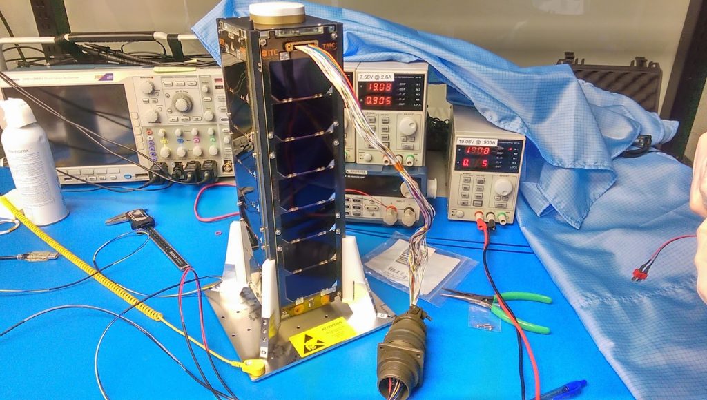
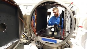
In addition to all the sensors inside the spacecraft, more were applied externally to ensure proper calibration of those mounted on each of the solar panels. The spacecraft had to sit on special spacers made from a composite material. STF-1 in the TVAC chamber is shown below.
 Once everything was setup, the chamber was placed under vacuum and heated to 60 degrees Celsius or 140 degrees Fahrenheit for over six hours! This ensured that all components had enough time to reach that temperature and proved that they would still function after exposure to those extreme conditions. After that, four simulated orbits were performed. The chamber would cycle from 50 degrees Celsius to 0 degrees Celsius or freezing. Tests were performed throughout these procedures and all passed! STF-1 is currently undergoing preparations for vibration testing in a couple of weeks.