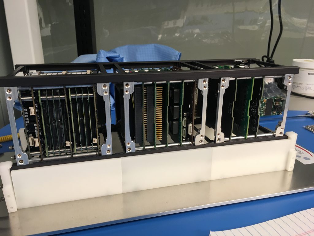
Once all the components that were ordered as a result of the integration fit check arrived, the assembly and wiring process could begin. Previously each unit or individual cube had been crudely spaced using spare standoffs and lots of washers. New standoffs of the correct sizes replaced these and allowed for much easier assembly of the entire unit, as well as fit into the chassis after the deep cleaning each component received in preparation for environmental testing. 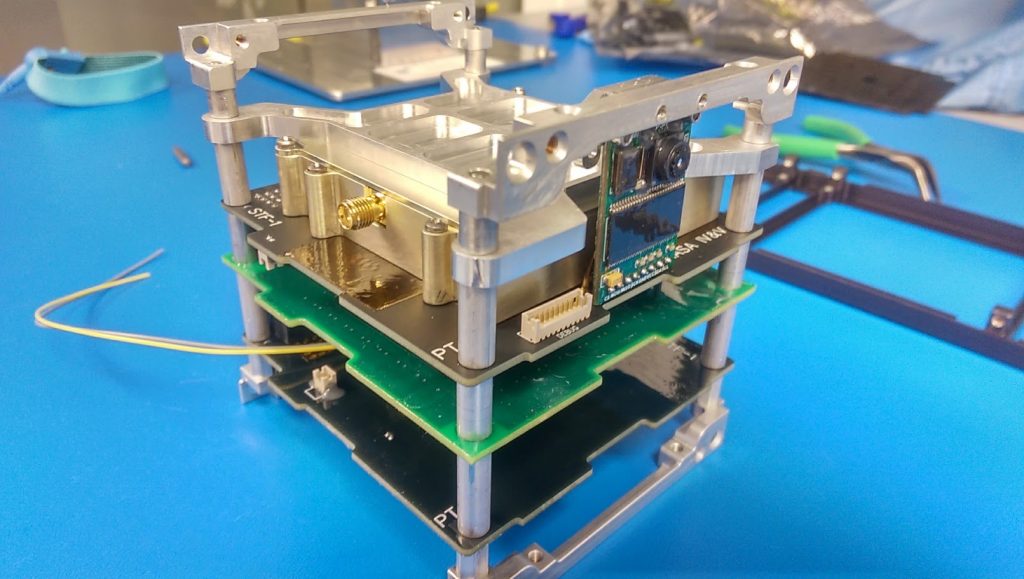
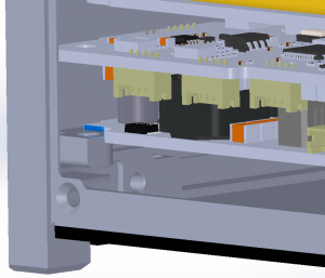
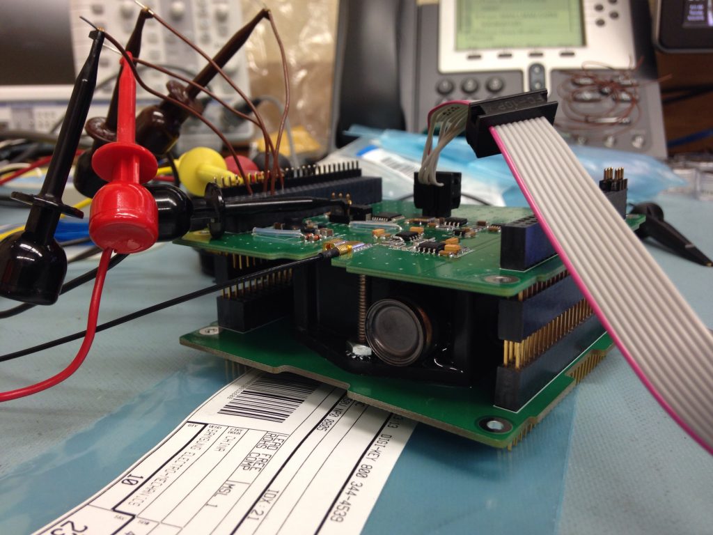
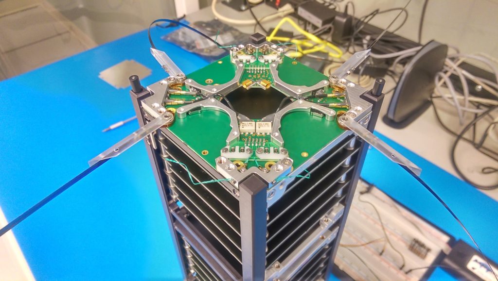
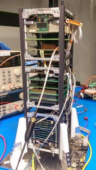
Although each of the components are connected to the stack or back plane of connectors making up the spine of the spacecraft, additional connections are required to reach external components as well as to jump certain things into or out of the spine. The image below shows a large portion of these connectors completed, but does not yet include all of the solar panels that will provide the power needed to charge the batteries and run the experiments on-board. The stack connectors are on the opposite side of the camera.
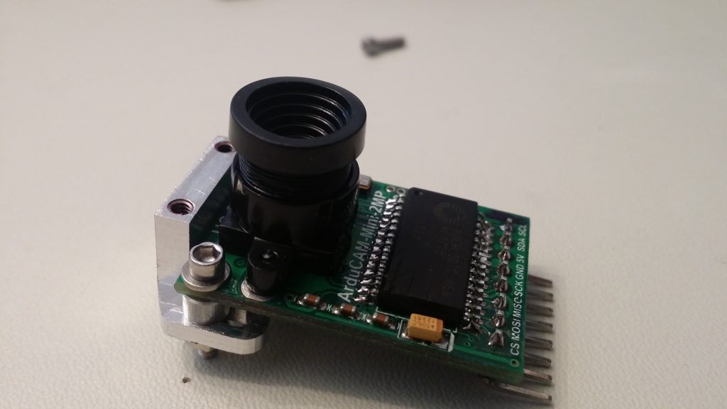
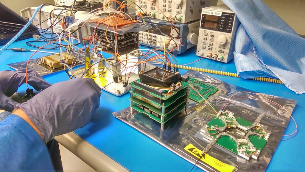
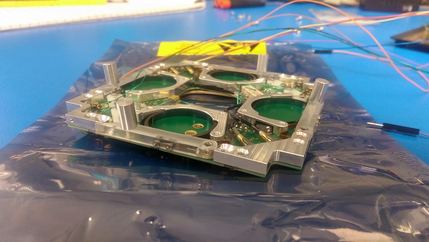
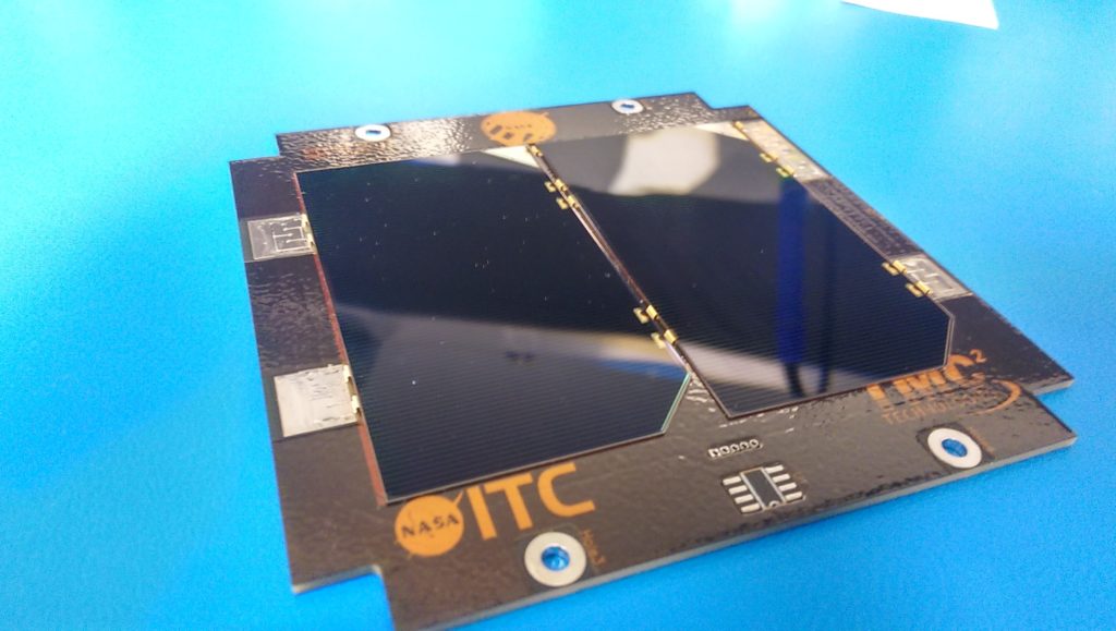
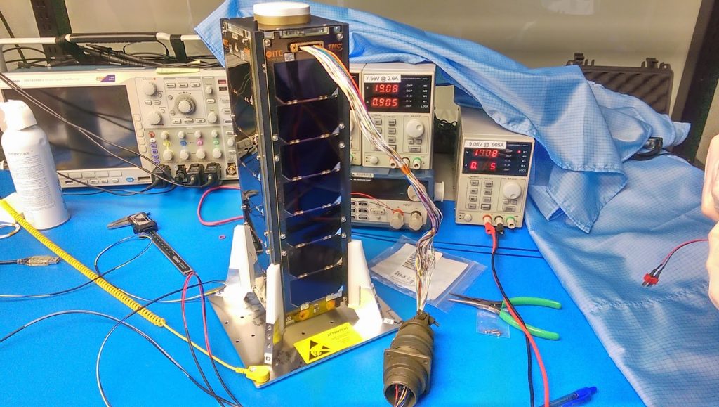
The electrical power system wiring harness proved to be the most difficult as each face needed to be able to connect before you mounted the panel to the spacecraft. This required lengthening some of the planned cables and defining an appropriate assembly and disassembly process. The solar panel that has the whole for the camera will always go on last and be the first to come off should we need back into the spacecraft. STF-1 with the solar panels, debug port, and remove before flight connectors is shown below. Some packing of tools and extra hardware is required prior to a trip to Goddard Space Flight Center (GSFC) for a week long thermal vacuum test, but for now all systems are operational.
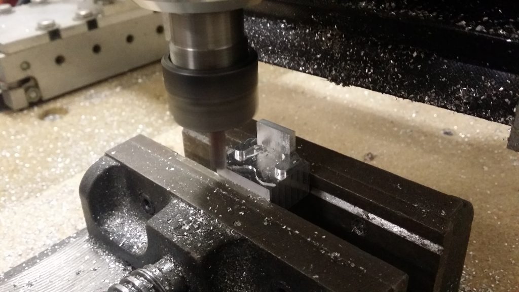
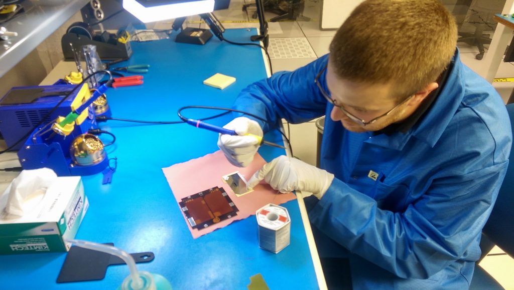
 After all the measurements were taken and some modifications settled upon, the entire satellite needed to be disassembled for cleaning and conformal coating prior to final integration for environmental testing.