Assembly and Wiring

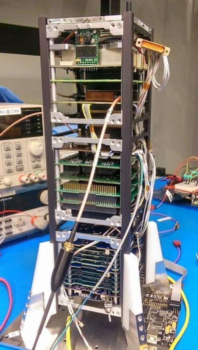
Once all the components that were ordered as a result of the integration fit check arrived, the assembly and wiring process could begin.  Previously each unit or individual cube had been crudely spaced using spare standoffs and lots of washers.  New standoffs of the correct sizes replaced these and allowed for much easier assembly of the entire unit, as well as fit into the chassis after the deep cleaning each component received in preparation for environmental testing.  stf1_stack_top
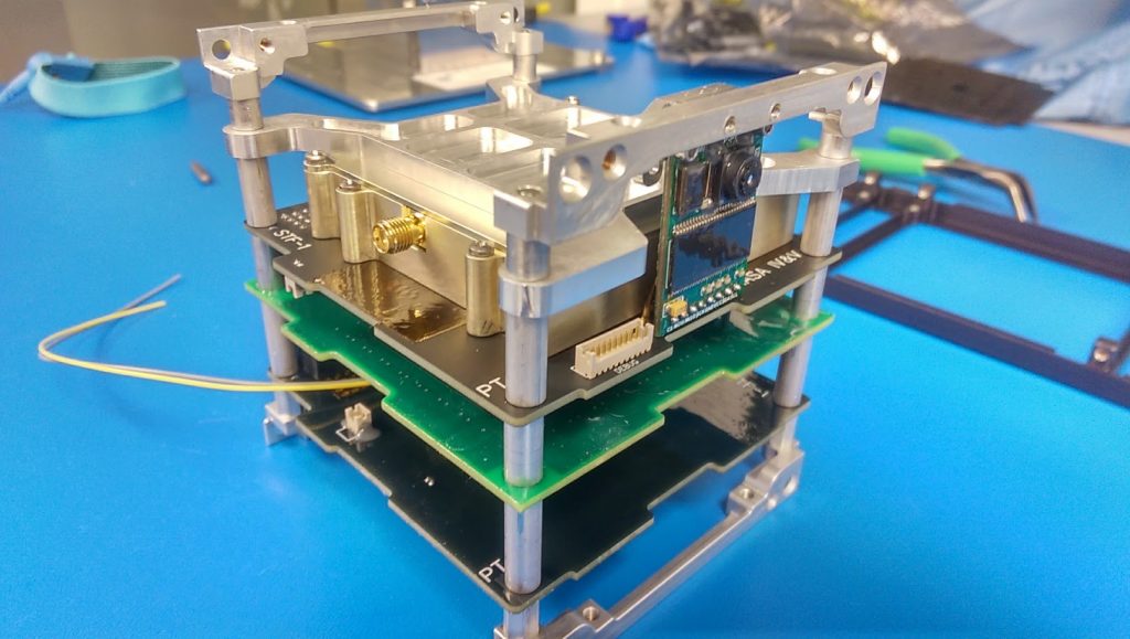
Although each of the components are connected to the stack or back plane of connectors making up the spine of the spacecraft, additional connections are required to reach external components as well as to jump certain things into or out of the spine.  The image below shows a large portion of these connectors completed, but does not yet include all of the solar panels that will provide the power needed to charge the batteries and run the experiments on-board.  The stack connectors are on the opposite side of the camera.
stf1_integration (2)

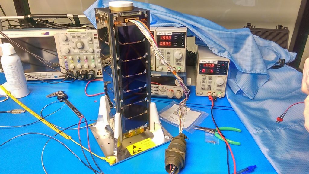
The electrical power system wiring harness proved to be the most difficult as each face needed to be able to connect before you mounted the panel to the spacecraft.  This required lengthening some of the planned cables and defining an appropriate assembly and disassembly process.  The solar panel that has the whole for the camera will always go on last and be the first to come off should we need back into the spacecraft.  STF-1 with the solar panels, debug port, and remove before flight connectors is shown below.  Some packing of tools and extra hardware is required prior to a trip to Goddard Space Flight Center (GSFC) for a week long thermal vacuum test, but for now all systems are operational.
stf1_flight

Integration Fit Check

The STF-1 team has been hard at work completing an integration fit check.  This process took an entire day and was turned into a time-lapse for you to see.  Unlike what is shown in the video, each stack had to be assembled multiple times in order to add or remove different combinations of washers and spacers in order to achieve the required fit.

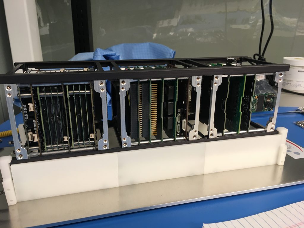
Upon completion new measurements were taken for the entire spacecraft.  These will be used to determine the lengths required for cables and new spacers to be ordered for the flight integration test only weeks away.  The final product can be seen in a close up below.

STF1_Integration_FitCheckAfter all the measurements were taken and some modifications settled upon, the entire satellite needed to be disassembled for cleaning and conformal coating prior to final integration for environmental testing.
FlatSat Tear-down

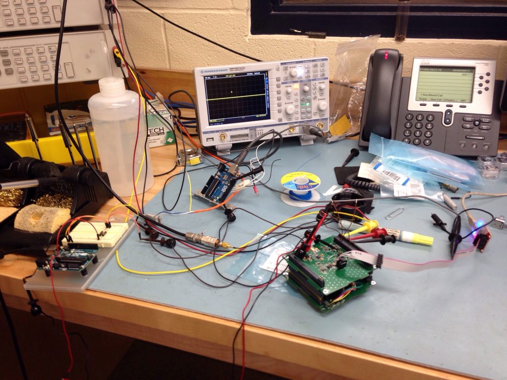
With all of the STF-1 components acquired, the team has been working on functional testing of each.  Once the component was checked out and proven, it was integrated into a FlatSat version of the spacecraft.  The FlatSat includes all components and experiments, but laid out on a single lab bench instead of stacked together allowing for modifications and checks of each component to be performed with more ease.  Upon completion of testing in the FlatSat configuration the STF-1 team was tasked with the tear-down process.  With all the wires needed to connect all the components and all the pieces themselves being very sensitive, this task had to be taken seriously.  A time-lapse was taken of this process and is shown below.


Every Millimeter Matters

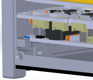
The STF-1 spacecraft is so small that on multiple occasions, measurement errors of less than a quarter millimeter have caused concern.  One example of this occurred during the model review of the battery unit.  The EPS was colliding with the chassis as highlighted in the image below in blue.  The fix for this was as simple as ensuring the connectors were fully mated, but even adjusting the EPS this much caused the entire spacecraft to have to be rechecked. every_mm_maters

To provide some scope, on average a grain of sand is 0.5 millimeters and the head of a pin is 2.0 millimeters.  The STF-1 spacecraft has some very small components with low tolerances.  Even forgetting to include washers will cause issues during assembly.  Currently the STF-1 team is focusing very hard to ensure we use every piece allocated as the spacecraft gets constructed unit by unit from the top down.

Camera Mount

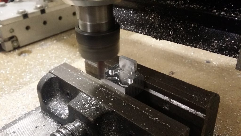
The STF-1 team has been hard at work constructing a custom mount for the camera this week.  This mount will keep the camera firmly in place throughout the vibrations experienced during launch.  A Computer Numeric Control (CNC) machine was utilized to cut the mount out of a solid aluminium block.  The picture below displays a close-up of the machine in action!

2017-01-18 13.37.28

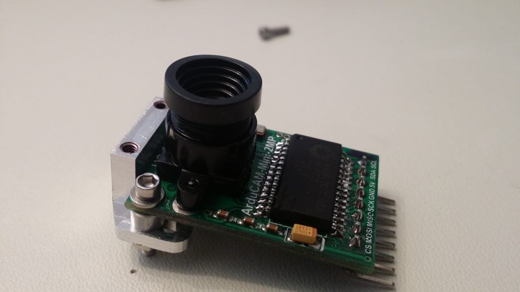
The CNC machine takes in a special type of code, G-Code, which provides instructions for how to cut the part.  This includes things like where to move, how fast to move, what path to follow, and what bit to use for the operation.  G-Code is typically automatically generated from a computer model to ensure that the dimensions of the component are correct.  The final product can be seen attached the the ArduCAM OV2640 Mini below.  The mount will attach directly to the side of the chassis while the camera will plug into the special services card allowing it to communicate with the computer.

2017-01-19 13.09.26

GSFC Small Satellite Collaboration and STF-1 Lab Tours

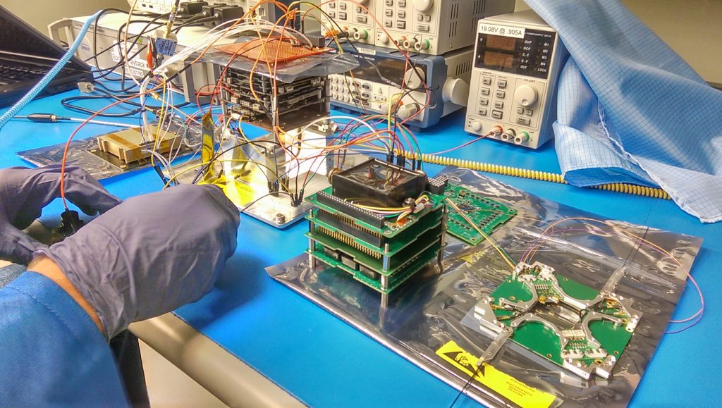
The STF-1 team has been involved with a number of small satellites missions from Goddard since the proposal process.  Similar components were utilized across missions to provide additional support and spare parts between us.  Last week the STF-1 team was called upon to share the engineering test unit (ETU) electrical power system (EPS) from ClydeSpace.  In order to do this the flat sat had to be taken apart.  The “flat sat” is a technique used to test how all the components work with one another on a table-top instead of in a chassis.  This allows for more simple debugging and setting up of test configurations.  An example picture of what this looks like is below:

IMG_20170117_103425

With all of the components taken apart, it was the perfect time to do some impromptu tours for our co-workers at NASA IV&V.  Approximately 30 people came to visit the clean room and get a feeling for the actual size of the components and spacecraft itself as well as ask interesting questions.  STF-1 has once again created a flat sat, but this time with a battery in the loop as well to provide yet another data point for testing.  Once a few more tests are complete, it will be time for integration into the chassis!

CSEE Payload Testing

The STF-1 team has been busy over the past weeks working with the Computer Science and Electrical Engineering (CSEE) department at West Virginia University.  During this time hardware, firmware, and software updates had been made to allow for integration of the payload into the STF-1 stack. The video below shows one of the two boards in the payload triggering, or flashing the LEDs, as a response from the flight computer.

The LEDs shown are specially made using Gallium III-V Nitride-based materials at WVU.  The payload is set to test the amount of shielding needed in the harsh environment of space to allow use for short-range distance measurement and shape rendering.  The second board (not shown) utilizes photo diodes to provide the measurements needed for the experiment over the duration of the mission.

WVU Physics and Astronomy Space Weather Instrument Testing

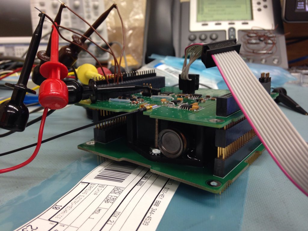
The STF-1 team continued progress on various components of the spacecraft during the past week.  The WVU Physics and Astronomy department is contributing an instrument to analyze space weather in the ionosphere.  The instrument contains a Langmuir Probe for measuring properties of plasma and a Geiger counter for measuring ionizing radiation.

img_3948

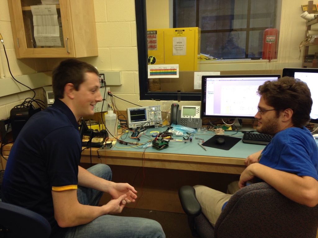
During the past week, the final flight board assembly was completed and testing of the firmware for the microcontroller and of the hardware was executed in the physics lab in White Hall at WVU.  The various components that will eventually comprise STF-1 each must be tested in isolation prior to being ready to integrate into the chassis and then the entire spacecraft being tested.

The pictures below show instrument testing at the lab.  If you look closely, you can see the cylindrical end of the Geiger counter sticking out between the two circuit boards.  Note also the various leads connected to the board and the external instruments needed for performing stimuli and taking measurements during testing.  (Photo credits:  Mark Suder)

img_3954 img_4546

Antenna Deployment Test

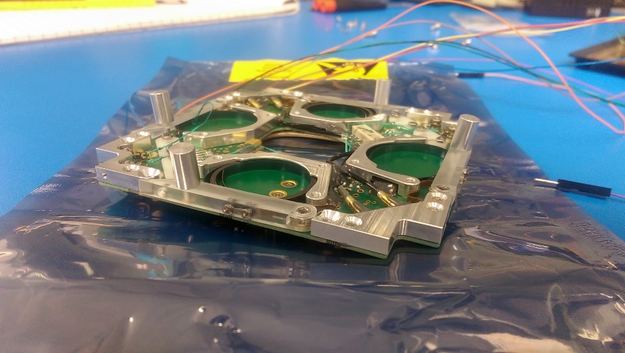
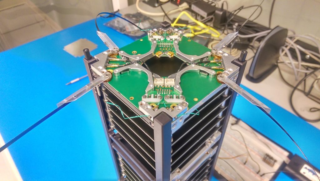
The STF-1 team has begun unit testing the ISISpace Antenna System (AntS) in the cleanroom this past week.  The AntS is made up of four individual elements that deploy when commanded from the on-board computer.  These elements can be in a multitude of configurations, but STF-1 will be utilizing the dual dipole.  This means the each antenna is linked with the one directly across from it.

stf1_ants_01

The picture above shows the antennas are rolled up and ready for deployment.  Each antenna has a burn-wire that holds it closed.  When activated the resistors underneath this wire will heat up and cause the wire to break and allow the springs to open the door.  Each antenna is actually the same material as a tape measure with similar properties.  STF-1 will use one dipole (or set of connected antennas) to communicate with the ground station and the other as a Langmuir probe to perform experiments for the Physics department at WVU.

stf1_ants_02

Each antenna can only be deployed twice, once on the ground and once in space.  Because of this, video was taken to document the process.

First Solar Panel Built

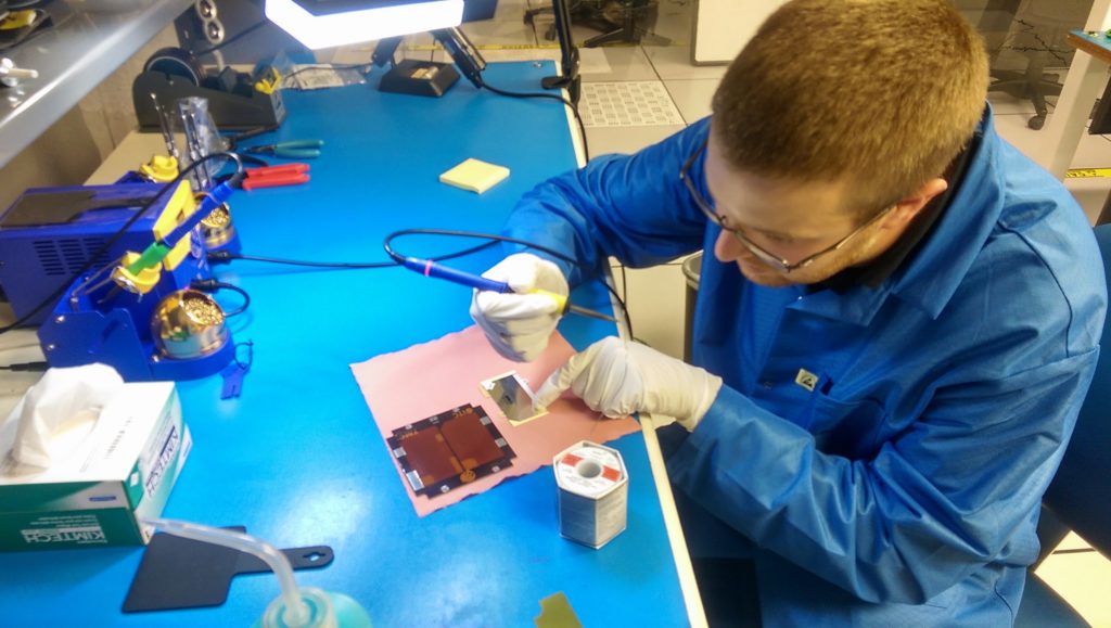
The STF-1 team made the decision early on to leverage the efforts of another Goddard CubeSat mission, Dellingr, in components used.  This included custom designed solar panels created in house.  Interns at GSFC spent a summer perfecting the process of designing and building these solar panels.  This includes printed circuit board (PCB) design, construction materials and process, as well as how to test a panel is fully functional and ready for flight.

IMG_20160824_144712

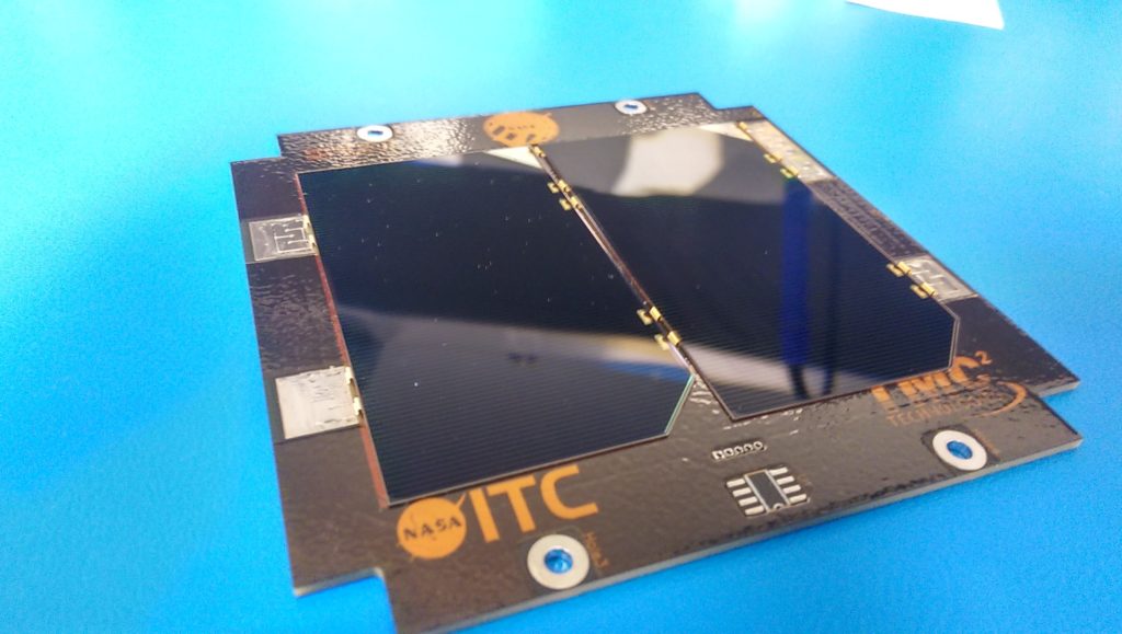
The picture above shows STF-1’s technical lead, Matthew Grubb, preparing to solder the silver connector onto the solar cell to allow for a connection to the PCB.  STF-1 will have up to seven of these cells connected in a row attached to the board only by the four solder pads and a special type of tape underneath each cell.  Below you can see the completed solar panel and these connections.  The temperature sensor (empty pad in the picture) will be added and tested before flight as well.

IMG_20160824_155537